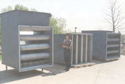


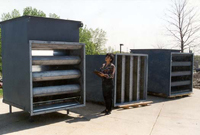
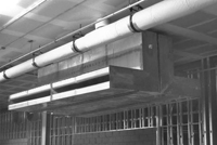
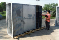
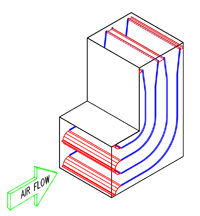
Elbow Silencers

Pressure Drop
The expected static or total pressure drop across the silencer allowing for adequate pressure recovery, when silencers are mounted close to fans, downstream elbows, etc., pressure drop corrections are required. These can be obtained from the guideline chart.
Insertion Loss
The decrease in noise level due to the insertion of the silencer into the duct system.
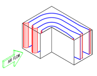
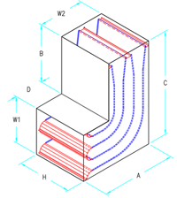
Silencer Length = Length Along Centerline = A+B = C+D
Selection Procedure: (when W1=W2)
If Elbow Size is Known:
Step 1. Establish dimensions A, B, C, D, W1 and W2
Step 2. Calculate approach velocity to silencer
Step 3. Calculate silencer length; length along centerline equals A+B = C + D; when W1 = W2
Step 4. Using W1, establish a set of possible module widths where;
X = (W/No. of Modules) ≤ 24" (610mm)
Step 5. Establish your Insertion Loss(IL) and change in pressure criteria
Step 6. Using the accompanying "Acoustic & Pressure Drop Ratings" chart, select the largest member of the module width set that satisfies both IL and chang in pressure criteria
Step 7. If no module seems able to satisfy your IL criterion within the specified pressure drop (change in pressure), alter the W1 and/or "H" values of your approach ductwork to reduce approach velocity
Step 8. Repeat steps 1 thru 6
If Elbow Size is Unknown:
Step 1. Establish your Insertion Loss(IL), change in pressure and approach velocity criteria
Step 2. Using the accompanying "Acoustic & Pressure Drop Ratings" chart, select the largest module size that satisfies your criteria
Step 3. Establish dimensions A, B, C, D, W1 and W2 to suit the space available
Step 4. If step 3 seems impossible:
(a) Alter your change in pressure and/or approach velocity
(b) Repeat steps 1 thru 4
| Elbow Modules | ||
|---|---|---|
| Module | Width (in) | Width (mm) |
| 10 | 10 | 254 |
| 12 | 12 | 305 |
| 14 | 14 | 356 |
| 16 | 16 | 406 |
| 18 | 18 | 457 |
| 20 | 20 | 508 |
| 22 | 22 | 559 |
| 24 | 24 | 610 |